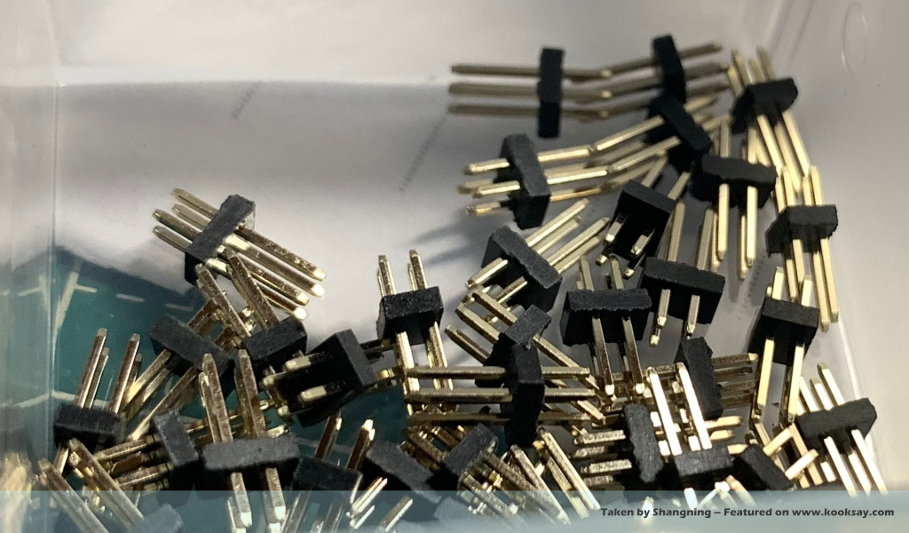
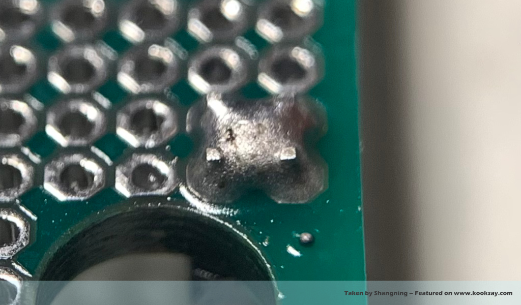
Hand soldering 2.54mm pin headers is easy, but soldering 1.27mm pin headers is much more difficult — at least that’s true for me. When soldering 1.27mm pin headers, the solder doesn’t behave as it usually does. Instead of spreading out to each pin’s pad, it tends to gather into a large solder blob that bridges several adjacent pins and wraps around them all.
When solder bridges occur, experienced DIYers often use the soldering iron tip and some flux to remove part of the solder blob, allowing the remaining solder to separate thanks to the pulling force of the pin legs. However, this technique becomes much less effective when dealing with 1.27mm pin headers. The reason is that the commonly used 1.6mm thick PCBs aren’t designed for 1.27mm headers, so the pins don’t protrude through the PCB surface. As a result, there’s no exposed copper leg to help separate or draw the solder apart.
So the best soldering strategy is to avoid letting a large blob of solder cover the pins in the first place. Instead, use the smallest possible soldering iron tip along with finer solder wire — such as 0.5mm — and perform spot soldering on each pin individually. This is easier said than done, though, and in practice, many difficulties arise:
First, due to the very tight 1.27mm pin spacing, even slight hand tremors get amplified through the soldering iron and solder wire, making it difficult to precisely align the iron tip, solder wire, and pin onto a single point. Second, since the pin header is inserted from the opposite side of the PCB, you need an extra hand just to hold it in place, leaving you feeling like two hands are not enough. The most troublesome part is that these 1.27mm pins require only a very small amount of solder — too much, and you get bridging; too little, and the flux in the solder evaporates quickly, reducing flow and making it hard for the solder to adhere to the pad properly.
Even if all the above issues aren’t a problem, there’s still the worst one: it’s very hard to ensure that the pin header is soldered vertically, since it’s on the opposite side of the PCB and you can’t observe it during soldering.
This is where using solder paste for ‘pre-fixing’ the pin header really shows its advantages. Simply dip the pin header (or female header) into solder paste so that each pin picks up a bit of paste, then insert it into the PCB. You’ll notice that the viscosity of the paste acts like a temporary adhesive, holding the header in place and preventing it from falling out when the PCB is flipped over.
With this method, there’s no need to feed solder wire directly to the pad. Instead, pre-melt a small bead of solder on the soldering iron tip. Because of the high temperature of the iron, the flux in the solder will fully evaporate, leaving a pure solder bead clinging to the tip.
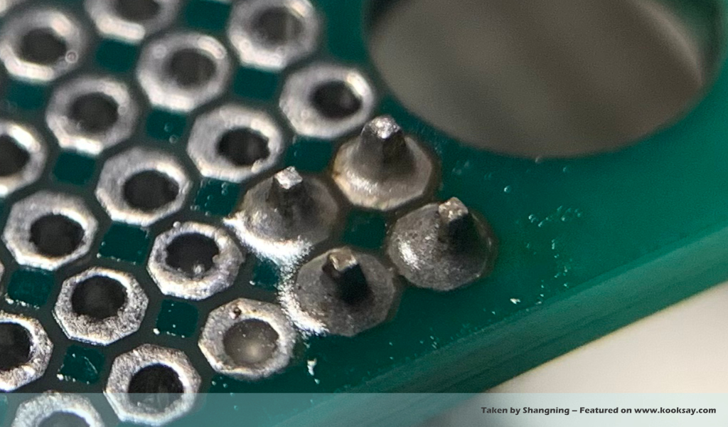
Quickly touch this molten bead to the pad. Thanks to the flux remaining on the exposed pin (no matter how much is exposed), the solder will rapidly wick down into the pad, via holes, and around the pin, completing the solder joint.
You don’t need to worry about solder bridging between pads, because this method makes bridging very unlikely — the key reason being that only the exposed pin has flux on it, while the pad surfaces and areas between pads are flux-free, so the molten solder only flows where the flux is present.
This soldering technique not only frees up both hands, but also helps ensure that the pin header is straight and vertical. Each pin receives just the right amount of solder, making it a beginner-friendly and hobbyist-recommended approach.