Introduction
Dupont wires and alligator clip cables are commonly used in prototyping circuits and conducting quick experiments due to their affordability and ease of use. For electronics enthusiasts, these are often the first and most frequently used jumper tools.
However, as circuit complexity increases, along with signal frequencies, current, and power demands, you may start noticing strange issues: unstable circuit behavior, intermittent connections, or even inexplicable system failures. Upon closer investigation, the root cause may lie in the wires themselves.
The core of the problem often comes down to overly thin conductors, excessive length, or poor terminal contact.
In this article, I’ll “dissect” these two common types of wires — both physically and in terms of user experience — to explore when and how they can become hidden risk points.
Dupont Wires
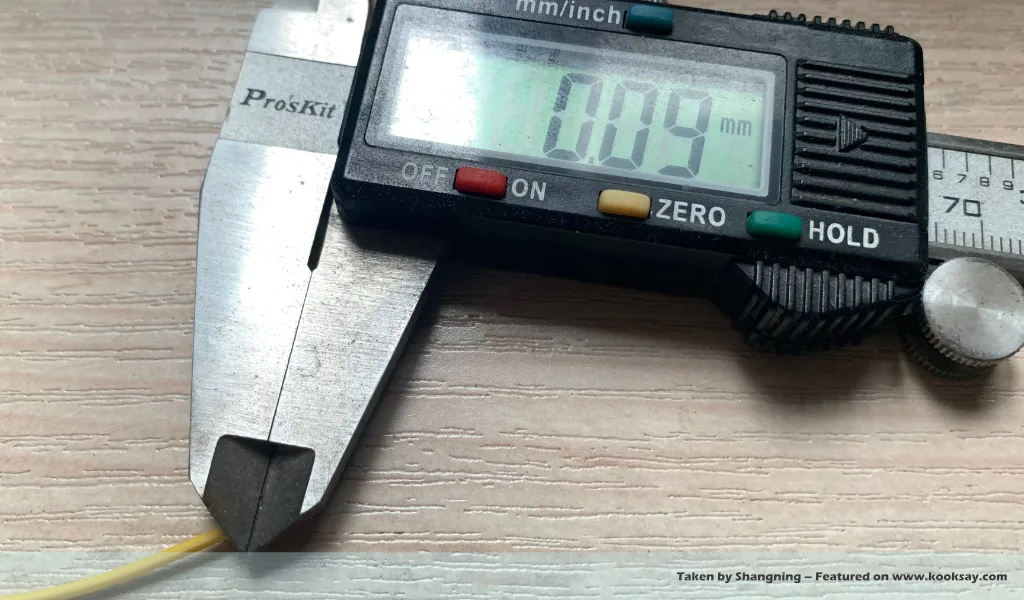
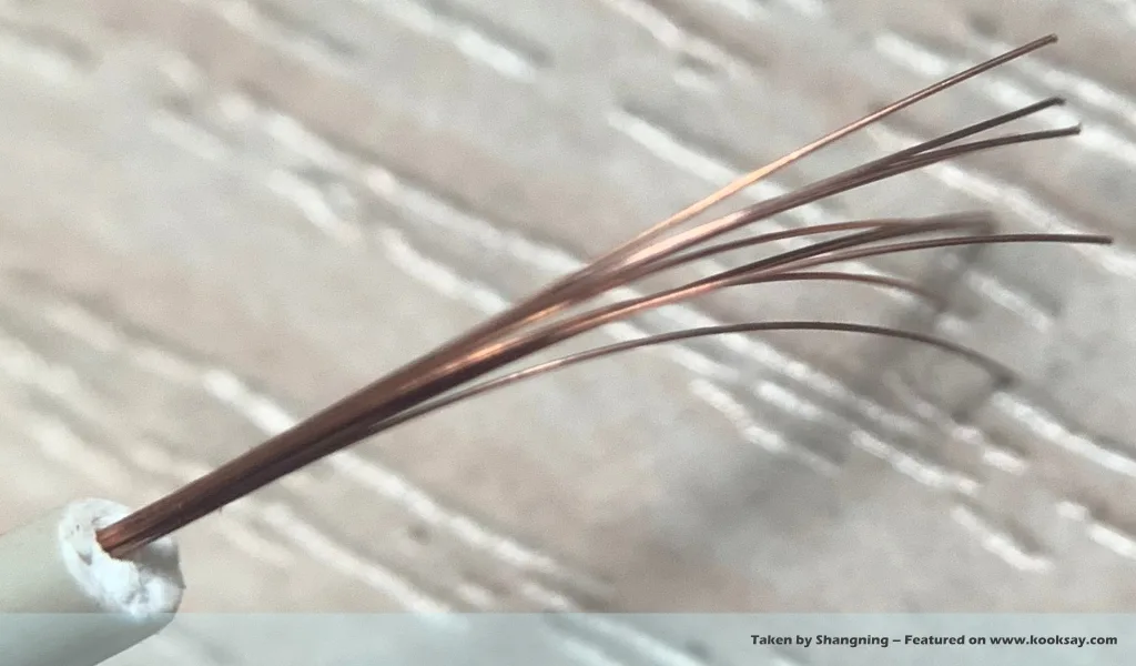
The Dupont wire I examined contains seven strands of wire, each with a diameter of 0.09 mm. Therefore, the total cross-sectional area of the conductors is:
7 × π × r2 = 0.0445 mm2
which is equivalent to a single conductor with a diameter of 0.238 mm.
These slender wire strands are usually made of tinned copper. But for the sake of calculation, let’s assume they are pure copper, using a conductivity of 5.96 × 10⁷ S/m.[1]
With a length of 180 mm, the resistance of the Dupont wire is:
R = L / (σ × A) = 0.18 / (5.96×107 × 0.0445×10-6) = 0.0679 Ω
This might seem small, but in certain circuits, this resistance is not negligible.
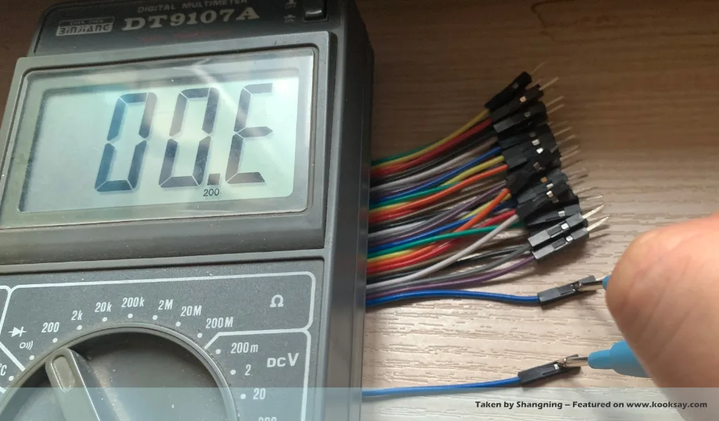
Moreover, this estimate is optimistic, as it assumes pure copper. In reality, the wires are tinned copper, and the terminals at both ends are often made of lower-conductivity metals. As a result, even with a regular multimeter, the resistance of a Dupont wire can be measured. The specific one under discussion here shows a visibly high resistance of 0.6 Ω.
Alligator Clip Jumper Cables
Commercially available alligator clip cables, even the thinnest ones, appear noticeably thicker than the thickest Dupont wires.
The sample I disassembled contains 10 wire strands, each with a diameter of 0.1 mm. This already feels more robust than the Dupont wire previously examined.
Let’s again estimate its properties using the same method:
Cross-sectional area = 10 × π × (0.05)2 = 0.0785 mm2
nearly double that of the Dupont wire (0.0445 mm2). This wire gauge, which appears to correspond to AWG 28, is already capable of carrying a relatively large current.[2] Treating it as two Dupont wires in parallel, the resistance would drop from 0.068 Ω to 0.034 Ω.
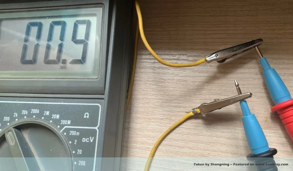
Each end of the alligator clip cable has a spring-loaded “jaw”, which provides firmer contact than the weakly pressed connectors on Dupont wires. Therefore, in theory, they should outperform Dupont wires electrically.
However, these are still low-cost consumables, and the metal used in the clips isn’t necessarily better. Multimeter measurements reveal that this wire has a surprisingly high resistance of 0.9 Ω.
Let’s also calculate the equivalent PCB trace width of this wire. Assuming an FR4 PCB with 1 oz copper (35 μm thick), the equivalent PCB trace width is:
w = 0.0785 / 0.035 = 2.24 mm
This seems quite wide — an impressively broad “trace”.
Preliminary Conclusion
By now, you might have noticed some issues:
- Whether Dupont or alligator clip wires, the actual core diameters often don’t match the nominal AWG sizes. (This might be due to purchasing low-quality products.) The prudent approach is to measure and re-verify each new batch of wires you receive.
- The actual resistances of both types are significantly higher than theoretical calculations. This may be due to product quality, but more likely because the terminal metals themselves introduce additional resistance into the circuit.
Practical Impact of Power Line Loss
Suppose you have a circuit powered by an external lithium battery, connected to a PMU (Power Management Unit) chip that boosts the 3.7 – 4.2V battery voltage to 5V and supplies the load.
Under light loads, everything appears fine. But what happens when the load increases and demands 5V at 300 mA?
If the PMU outputs 5V @ 300 mA with 92% conversion efficiency, it needs to draw nearly 400 mA from the 4V battery.
Now let’s consider the voltage drops caused by the wire resistances:
Dupont Wire:
Ideal voltage drop: ΔV = 0.0679 Ω × 400 mA = 27.16 mV
Actual voltage drop: ΔV = 0.6 Ω × 400 mA = 2.4 V
Alligator Clip Cable:
Ideal voltage drop: ΔV = 0.034 Ω × 400 mA = 13.6 mV
Actual voltage drop: ΔV = 0.9 Ω × 400 mA = 3.6 V
If the battery starts at 4V, the PMU sees only less than 2V (with Dupont wire) or even less (with alligator clips). The PMU reacts:
What? The battery voltage is only 1.6V? That’s way below the undervoltage threshold! I must cut off the power to protect the battery! – PMU Chip Thinking
And just like that, your circuit shuts down.
The Ground Wire Problem
The previous section showed how using these wires as power lines causes issues at high current. Now, let’s look at what happens when they’re used as ground wires — taking the seemingly more robust alligator clip cable as an example.
Although it’s thicker and equivalent to a 2.24 mm wide PCB trace, that’s still just a wire — not a ground plane. It may be adequate for power delivery, but as a ground, it’s lacking.
A single 2.24 mm-wide trace is not enough to ensure equipotential across the circuit. When used to connect ground across a breadboard, long and sparsely laid-out ground wires create the equivalent of separate “roads” to a distant Roman forum. On these roads, interference and high-frequency signals can cause voltage differentials — ground bounce or drift.
If one of these wires connects to a chip’s feedback or reference pin, the potential discrepancy can cause false readings and malfunction.
Conclusion
This article outlines the power integrity (PI) issues that Dupont wires and alligator clip cables can introduce. At high frequencies, they can also degrade signal integrity (SI) due to increased inductive impedance.
In short, when your circuit behaves strangely, don’t forget to consider the wires you’re using. If you’re using these types of cables — check them first.
Reference
- ThoughtCo, Table of Electrical Resistivity and Conductivity, https://www.thoughtco.com/table-of-electrical-resistivity-conductivity-608499
- PowerStream, American Wire Gauge Chart and AWG Electrical Current Load Limits, https://www.powerstream.com/Wire_Size.htm