I’ve spent several months working on the design of this product, and along the way, I’ve learned a lot of new things. Now, the design of the signal part is nearing completion, and I’ve started working on the power supply part.
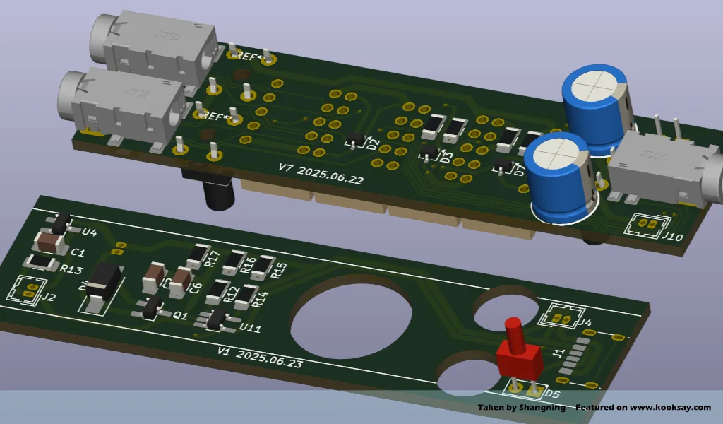
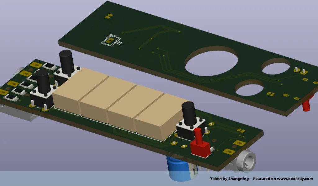
Today, I completed the PCB layout and planning for both the signal part (Version 7) and the first version of the power board (Version 1), and I’m preparing to send them for prototyping and testing.
As mentioned in previous articles, compared to the earlier Version 5, this iteration mainly improves how muting is handled — specifically, by changing the method of disconnecting the ground. In fact, I previously noted that trying to mute audio by disconnecting the ground is incorrect. The proper method should be to disconnect the left and right audio signal lines directly.
The power board design and production is the focus of this trial and has been my main area of effort over the past week.
At first, I thought the power section of this product would be relatively easy — I assumed a soft-pack lithium battery would be sufficient, especially since lithium battery management chips are now very mature. However, the reality turned out to be more complicated than I expected.
This hardware is being designed with the intention of becoming an actual “product,” and if it is to be treated as such, then using an internal soft-pack lithium battery becomes problematic. The main issue is that products with built-in soft lithium batteries cannot be shipped by courier.
As a result, I considered many alternative solutions: switching to AAAA batteries, using coin cell batteries, or even giving up on batteries entirely and powering the device directly via USB…
But each power supply option had its drawbacks. After careful consideration, I finally decided to go with an LIR coin cell lithium battery. This may be the best compromise:
It allows the device to operate without being tethered to an external power cable, doesn’t require disassembly to replace batteries, and is subject to slightly less strict shipping regulations compared to soft-pack lithium batteries (even though it’s still lithium-based, it’s treated with slightly more leniency in logistics).
However, unlike soft-pack lithium batteries, this type of metal-cased coin cell battery cannot be charged using the more common charging methods. Therefore, I chose to use the MCP73831 for charging, the HX3120A for protection, and the DMP1045U-7 for power path management in order to achieve simultaneous charging and discharging.
Since I haven’t used this combination before, I’m not sure whether it will function as expected. Additionally, the current circuit design lacks a USB ESD protection mechanism. But for now, I’ve decided to skip that and proceed with verifying the basic functionality of the power module using the simplest soldering setup. If this scheme proves to be viable, I will then improve the power section by adding a USB surge protection module.
That said, using LIR coin cells also raises concerns — I’m not fully certain about their charging and protection mechanisms, and their capacity is quite small. Nevertheless, I’ve decided to go ahead and build this power module first. Any issues that arise in actual usage will be addressed and summarized after the trial.