Today, I’ve received the power PCB for this side project. However, some basic components such as resistors and capacitors have not yet arrived. Once all the ICs are in hand, I will proceed with soldering and testing to see if it performs as expected.
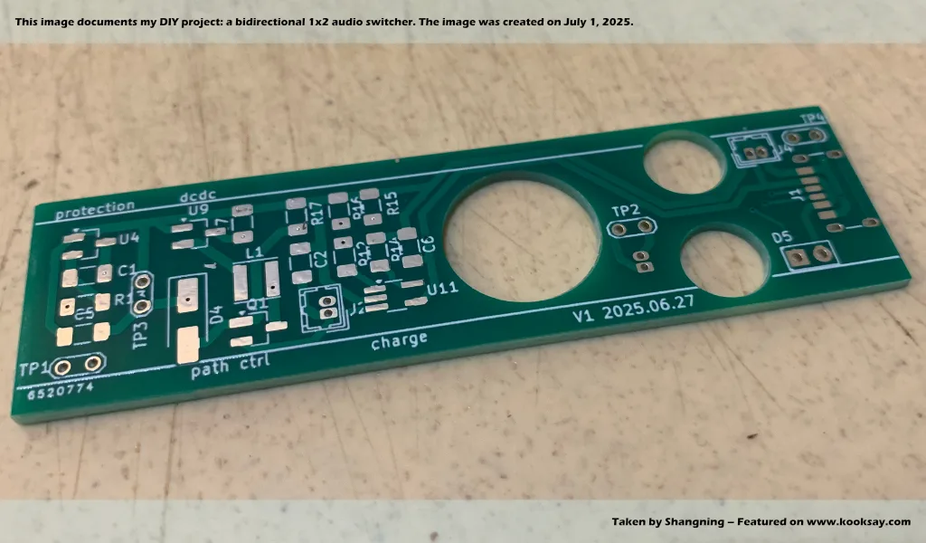
In addition to the two previously identified issues, receiving the PCB has raised a few new concerns:
USB Type-C Routing
Although I’m using a 6-pin footprint instead of the full 14-pin layout for the USB Type-C connector, I still find the routing in that area quite suboptimal. I’m wondering: since this is a very standard and commonly used connector, is there any well-established or widely accepted reference layout for its pin routing?
I’ve tried searching on Google for standard layout recommendations, but there doesn’t seem to be much discussion or guidance specifically for the 6-pin version of the Type-C connector. Perhaps that’s because the 6-pin configuration isn’t particularly demanding in terms of routing, so most designers just lay it out according to their own preferences or habits. I’m not entirely sure, but if time allows, I think it’s still worth examining this area more carefully.
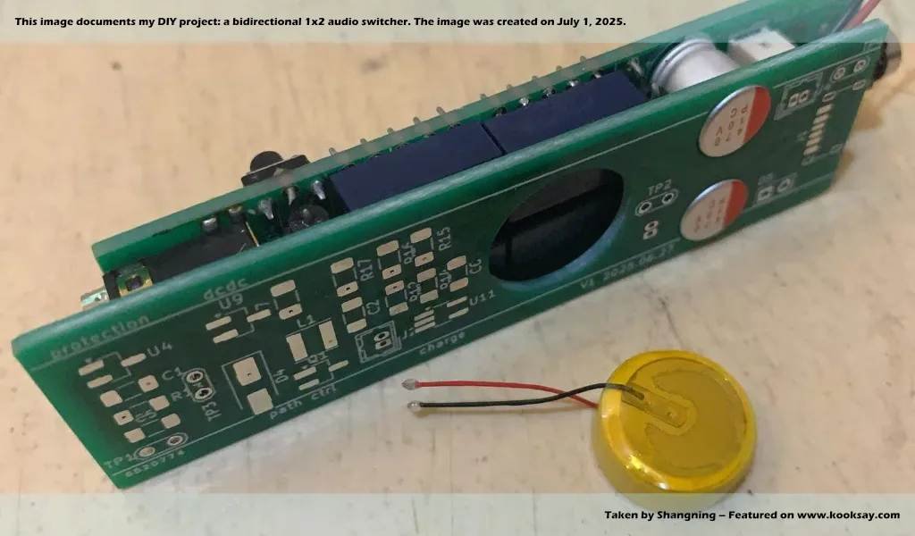
Connector Interference Issue
I may have overlooked a structural detail: my side project uses a stacked PCB design with two boards — top and bottom — connected via MX1.25-2P headers. However, during a preliminary placement test, I found that the MX1.25-2P connector might be causing mechanical interference. After functional validation, I plan to adjust this by switching from a vertical to a horizontal MX1.25-2P connector, which may provide a better fit.
For this project, I could completely do away with the MX1.25-2P connector and instead solder wires directly onto the PCB for power transmission. This approach would help prevent connector loosening during later usage and also reduce material costs. However, at this stage, since everything is still uncertain and the testing process inevitably involves repeated plugging and unplugging, the connector is probably necessary for now.
Previously Identified Issues (Reiterated)
These are repetitive but worth noting again:
- The USB section lacks a TVS diode for protection.
- The MCP73831/2 chip currently only drives a single red status LED. I need to revise the design to include both red and green LEDs so that charging and fully charged states can be clearly distinguished.
As for these known issues, I’m not too worried about them at the moment, since I already have some solutions in mind. What’s most urgent right now is to finish soldering the circuit and see whether its four core functions — charging, discharging, boosting, and protection — can operate properly.