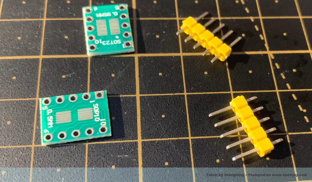
Here are two tips for soldering 2.54mm header pins that can help you keep them straight and vertical. Of course, these tips are not limited to 2.54mm headers — they also work well with other pitches or female headers.
Tip 1. Solder One Pin First — But Not the First Pin.
When soldering a row of header pins, it’s a common and helpful practice to start by soldering a single pin first. This allows you to reposition the header if it’s not perfectly vertical before committing to the rest of the pins. However, “solder one pin first” doesn’t mean soldering the first pin in the row — instead, you should solder a pin somewhere near the middle.
If you choose to solder the very first pin at the edge of the header, you’ll often encounter the following issue: the pressure from the soldering iron is applied unevenly across the header, causing it to tilt. You’ll likely have to reheat and adjust it multiple times to get the header flush against the PCB.
In contrast, if you start with a pin near the center of the row — for example, on a 5-pin header, solder pin 3 first — the pressure from the iron distributes more evenly, making it much easier to fix the header in place neatly from the beginning. After that, you can solder the remaining pins in sequence and achieve a nicely aligned, vertical finish.
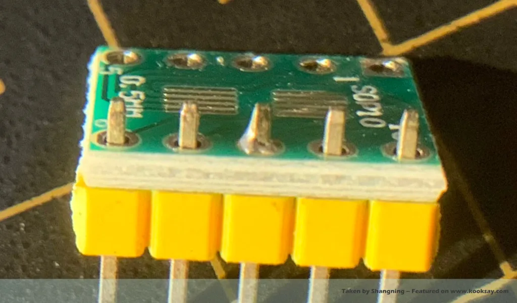
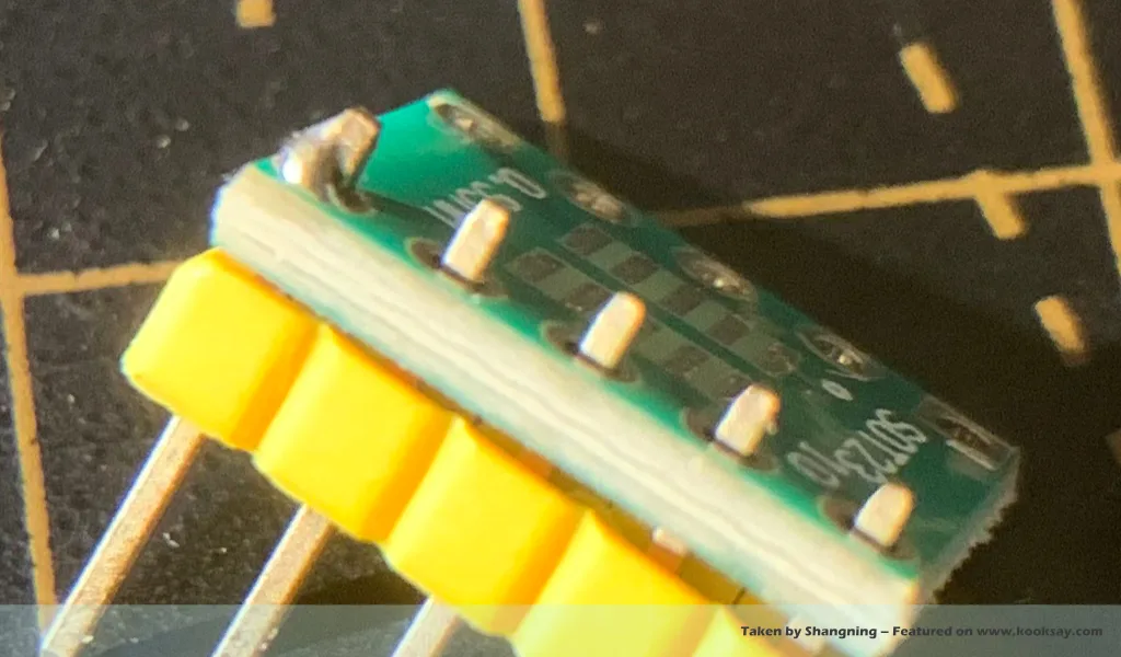
Tip 2. When designing your own PCB, use a snug-fit or self-locking hole pattern to secure the header and help keep it perfectly vertical.
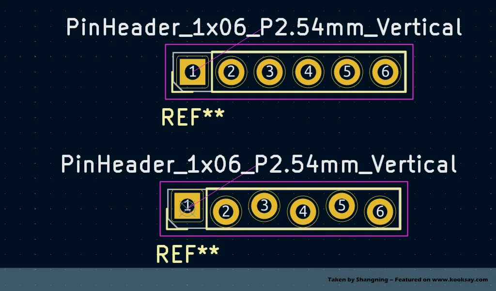
When designing your PCB, instead of using the standard header footprint, you can create a custom footprint by slightly reducing the hole diameters and arranging the row of holes in an alternating up-and-down staggered pattern. This forms a self-locking structure that greatly helps with the vertical alignment of the header pins. With this improved design, you can even achieve good mechanical retention of the header pins before soldering.
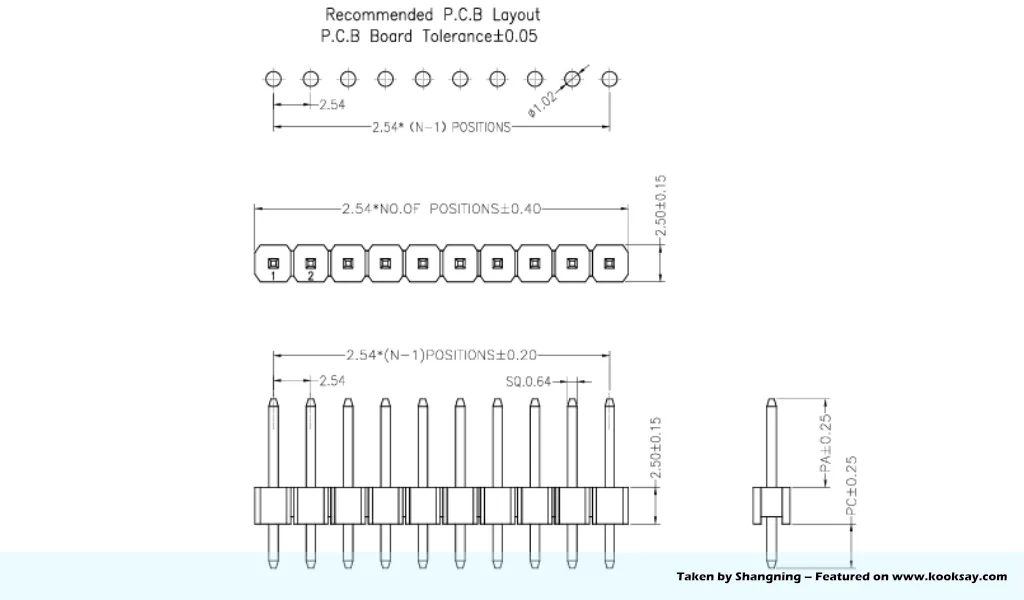
The standard footprint libraries in EDA software are typically drawn based on “recommended footprint specifications” designed to accommodate the widest range of manufacturing processes and equipment. These recommendations are often based on historical data and also take into account the convenience of automated production. However, with the significant improvements in modern manufacturing precision, we can now optimize assembly dimensions to much higher standards for manual soldering and even intentionally introduce slight interference fits to create self-locking structures.
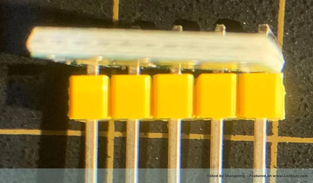
For example, with 2.54 mm pitch headers, the pin size is typically a 0.64 mm × 0.64 mm rectangular metal post, while the standard PCB footprint recommends using 1 mm diameter holes. In practice, we can reduce the hole diameter to 0.95 mm to minimize wobble and tilting during assembly.
Moreover, by staggering the holes slightly—alternating up and down by 0.1 mm along the row—we can introduce a light interference fit that effectively adds a self-locking effect during insertion. Once interference is introduced, automated assembly and soldering can become disastrous. However, for manual assembly and soldering, it can undoubtedly offer significant benefits.
If you don’t want to modify the footprint yourself, there are ready-made libraries you can use directly. For example, the SparkFun footprint library already includes this kind of optimized layout, specifically designed to make hand soldering easier for electronics enthusiasts.
For example, you can directly download and import SparkFun’s KiCad footprint library or Eagle footprint library for immediate use. This will greatly simplify and facilitate the soldering process that follows.